The simulator incorporates process models that simulate the physical and electronic behaviour of certain processes. When one of these models is activated on the interface of the simulator, the physical connection of the sensors and actuators of the process is imitated at the card inputs and outputs.
Figure 5, “Window of the process model of a DC motor speed control.” shows the window of a model of a DC motor speed control connected to an encoder.

This option simulates a motor whose power inputs is connected to the card DA1 output, and whose tachometer exit is connected to the AD0 input. It is possible to control the motor direction of turn using the digital output DO0. To know the real direction turn of the motor one can read the digital input DI0. Table 1, “Signals of the DC motor model.” summarizes signals of this model.
Table 1. Signals of the DC motor model.
| Signal | I/O | Type | Connection | Description |
| Motor power | Input | Analog | DO1 | from 1 to 4 Volts. Min to max. power |
| Motor speed | Output | Analog | AD0 | lineal, 0=0 RPM, 5 v.= 8000 RPM |
| Set direction | Input | Digital | DO0 | TTL, 0=clockwise, 1= ccwise |
| Get direction | Output | Digital | DI0 | TTL, 0=clockwise, 1= ccwise |
Figure 6, “Window of the process model of liquids tank.” shows the window of a liquids tank control model. It is possible to control a pump, a heater and valve.
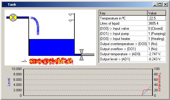
Table 2, “Signals of the liquids tank model.” summarizes signals of this model.
Table 2. Signals of the liquids tank model.
| Signal | I/O | Type | Connection | Description |
| Overheat | Output | Digital | DI0 | TTL, overheat = 1, normal = 0 |
| Overflow | Output | Digital | DI1 | TTL, overflow = 1, no overflow = 0 |
| Temperature | Output | Analog | AD0 | 0º to 100º C, tension lineal –5 to +5 volts |
| Level | Output | Analog | AD1 | 0 to 8000 liters, tension lineal –5 to +5 volts |
| Valve | Input | Digital | DO0 | TTL, open = 1, close = 0 |
| Pump | Input | Digital | DO1 | TTL, ON = 1, OFF = 0 |
| Heater | Input | Digital | DO2 | TTL, ON = 1, OFF = 0 |
Figure 7, “Window of the process model of dosage.” shows the window of a dosage of solids and liquids system.

Table 3, “Signals of the dosage system model.” summarizes signals of this model.
Table 3. Signals of the dosage system model.
| Signal | I/O | Type | Connection | Description |
| Posición contenedor | DI0 | |||
| Tolva rebose | DI1 | |||
| Tolva vacía | DI2 | |||
| Célula de carga | AD0 | |||
| Nivel tolva | AD1 | |||
| Electroválvula | DO0 | |||
| Señal entrada | DO1 | |||
| Señal salida | DO2 | |||
| Compuerta tolva | DA1 |
Note
Completar, altre dia será. Vorer més informació a especificació"mini"