This section describes step by step the use of the simulator. We suppose that a program prepared to use the simulator is available.
The first step is to run the prepared program. When the application runs the initialization function of the data acquisition card the simulation mechanism is triggered, then the dialog of the Figure 3, “Dialog to choose between the simulator or the acquisition card.” appears and we can opt to use the simulator or the acquisition card.
In this dialog we will be able to specify the IP address where the simulator is located, default option assume that simulator and application run in the same computer.
The simulator viewer simseny.exe must be running and the network protocol TCP/IP will be a requisite on both machines.

Figure 4, “Input and output signals viewer.” shows the SimSeny simulator signals viewer (simseny.exe) in operation. The simulator tries to imitate the acquisition data card at the electronic signals level that are available through its connectors. The viewer permits physical outputs to be shown and physical values to be entered in the simulated data acquisition card inputs, both for digital and analog signals.
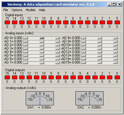
The simulated signals are:
Digital inputs: There are a total of 16 digital inputs. These are represented graphically by coloured shapes. When a mouse clicks on the shape, the colours and the represented logic value changes.
- Analog inputs:
There are 16 analog inputs. Any input is selected graphically in SimSeny by means of a scrollbar. To the right of each bar the analog value entered is shown.
- Digital outputs:
There are 16 digital outputs, which are graphically represented by coloured shapes. The shapes change in colour according to the value they represent, or logic level in the output.
- Analog outputs:
There are 2 analog outputs. In SimSeny, the voltage of the analog outputs can vary between [-15, 15] volts., which are represented graphically by a needle positioned on a graduated scale.