Last update: November 4th, 2010
Table of Contents
To have access to a really inexpensive data aquisition card (DAQ) could be cool for our gadgets.
The beloved DAQ must be USB compatible, because this interface is available in every today's computer, although this could imply a poor “real-time” behaviour.
I tried to find one, but with no success. I found that my best option for Microsoft Windows is the National Instrument's USB-6008, but it is very problematic to get it working on Linux.
For Linux, the USBDUXFast seems really fantastic and woks with COMEDI (great!), but no MWindows support :-(.
There are some Arduino based approachs, but they are not sufficiently mature and relies on USB-serial covertes like the FTDI chip.
Maybe the best option is to create one, so I decided to start an open project to create an ultra-inexpensive DAQ card benefiting of the new low cost, high performance USB-enabled microcontrollers.
These are the design requeriments of the CheapDAQ:
Really inexpensive. This can limit performance.
USB interface. But not dependent of this interface.
Compatible with most OSes. A must is Linux and Microsoft Windows, but should work on Embedded Linux and Windows CE/Mobile.
Compatible with National Instrument's LabView.
Drivers less. If posible, no extra drivers required to work with the DAQ.
COMEDI interface. Both for Windows and Linux. Enabling cross-platform development of data aquisition software.
Master-slave design.
We decided to accomplish the project in two phases. A "proof-of-concept" phase to get, as fast as posible, a working prototype, and a "target platform" phase where the definitive platform will be elected and a better performance achieved.
At this point, we can say that "proof-of-concept" of phase has finished with impressing results and we are redefining the implementation concepts in a multitier approach.
Next table summarizes the actual state of the project from the point of view of the master:
| Item | State |
|---|---|
| USB 8051 microcontroller interface | It works! |
| Microsoft Windows XP master | It works! |
| Microsoft Windows Vista master | skippednot tested |
| Linux (Ubuntu 8.04 and 10.04) host | It works! |
| MacOS master | not tested |
| National Instruments LabView for Windows | It works! |
| National Instruments LabView for Linux | not tested |
| COMEDI-like cross-platform library for Linux & Windows | It works! (thanks to Pablo Alaman) |
| real COMEDI integration | not started |
Next table summarizes the state of the project from the point of view of the slave (the DAQ). Note that the software is not mature enough:
| Item | State |
|---|---|
| gital Input | It works! (8051) |
| Digital Output | It works! (8051) |
| Digital Wave Output | It works! (8051) |
| Digital Frecuency Input | It works! (8051) |
| Analog Input | It works! (8051) |
| Analog Output | not available directly in the 8051 micro |
| PWM Output | It works! (8051) |
| 1-wire interface | not started |
| SPI interface | started (8051) |
| I2C/SMBUS interface | not started |
| LIN interface | - |
| CAN interface | - |
Lots of serial-enabled devices use protocols based on human-readable strings of characters. These strings can be written and read using a simple serial terminal emulator, allowing an easy validation of the implemetation.
Also I teach how to deal with this kind of protocols, so this can be a good platform for practicing these concepts.
For these reasons, the proposed protocol is:
Commands and data are always packetized in strings that start with ASCII char "#" and end whith ASCII char 0Dh (<CR>). This eases the search of messages.
Master-slave configuration. Only host can initiate communication.
Master commands are of the form "#CCCddddddd...ddd<CR>", where "CCC" is a string indicating the command, and "dddd...dd" are the associated parameters. All in human readable format.
Slave response can be (always must be a response):
"#!ddd...dd<CR>" if the command worked succesfully, and "dddd...ddd" is the returned data. "ddd...dd" can be empty, that is "#!<CR>" indicates OK.
"#?ee<CR>" if problems with the command. "ee" is the error code in hexadecimal.
Next table is a list of the implemented commands :
| Command | Description | |||
|---|---|---|---|---|
#DOPssvvvvvvvv<CR>
| Set the values vvvvvvvv=[00000000h - FFFFFFFFh] represented as a 32 bits hexa number of the digital outputs of the given subdevice "ss". If the device has less lines, only LSB part will will be applied | |||
#DOMssvvvvvvvvmmmmmmmm<CR>
| Set the values vvvvvvvv=[00000000h - FFFFFFFFh] represented as a 32 bits hexa number of the digital outputs of the given subdevice "ss", but using a mask mmmmmmmm=[00000000h - FFFFFFFFh] to define applicable pins, a bit with value 1 in the mask, lets the corresponding bit of the port to be modified.If the device has less lines, only LSB part will will be applied | |||
#DOLssllv<CR>
| Sets the value (v={0,1}) of a given line (ll=[00h-FFh]) of a given subdevice (ss=[00h...FFh]). | |||
#DIPss<CR>
| Returns the value vvvvvvvv=[00000000h - FFFFFFFFh] of a given digital port with subdevice (ss=[00h...FFh]). | |||
#DILssll<CR>
| Returns the value (v={0,1}) of a given line (ll=[00h-FFh]) of a given subdevice (ss=[00h...FFh]). | |||
#DOFsshhhhllll<CR>
| Generates a continuous digital rectangular signal of hhhh=[0001h-FFFFh] microseconds for the level high part and llll=[0001h-FFFFh] microseconds for the low level part. | |||
#DIFss<CR>
| Returns the measured frecuency vvvvvvv in Hz present in the subdevice ss. | |||
#PWMssdddd<CR>
| Generates a PWM digital signal for subdevice ss. The duty cycle will be ddd.d %. | |||
#AISsscc<CR>
| Returns the analog value present in subdevice ss and channel cc=[00h-FFh]. Actully returns the read milivolts vvvvv=00000-99999 at the given channel. |
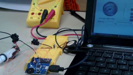
Because we are familiar with the Intel MCS-51 microcontroller family, we decided to use the USB-enabled microcontroller Silabs C8051F342 and ordered some Toolstick cards at Digikey. See bellow this wonderfull 10 EUR. DAQ card.

This microcontroller is a supercharged and enhanced derivative of the MCS-51 family. Apart from its impresive performance and its integrated peripherals, a key factor on the election has been its embedded debug circuitry
Any other low-cost USB microcontroller could be used, for example a Microchip's PIC18Fxxxx or an Atmel's AVR8, but I prefer to avoid manufacturer specific architectures.
Two key factors has been considered in electing the protocol for the USB link: wide compatibility with many OSes and a driver less design (that is, the OS includes a kind of standard driver).
I considered "virtual serial ports" as a posible approach. A lot of USB-enabled devices use this approach, and there are lots of projects (sucha as Arduino) that use a conversion chip like the FTDI or Silabs CP210x that creates virtual serial port to communicate classic UART peripherals with an USB enabled-host.
There is an standard virtual serial port specification for USB called "USB Communication Device Class Abstraction Control Model" (USB CDC ACM). All major OSes (Microsoft Windows, GNU/Linux, MacOS) include built-in drivers for this implementation, so incorporating this profile in the micrcontroller could provide easily a "virtual com port".
Searching the net I found an excellent implementation of this profile for the selected platform. Simply I downloaded the Tsuneo's implementation at this forum (includind .inf file for Windows). Thanks Tsuneo and the others.
Following the COMEDI representation of the DAQ systems, the signals has been grouped in subdevices. Next table is a summary of working subdevices and associated pins.
| Subdevice | Function | Pins |
|---|---|---|
| 00h | Digital I/O | Port P0 |
| 01h | Digital I/O | Port P1 |
| 02h | Digital I/0 | Port P2 |
| 03h | Digital I/O | Port P3 |
| 10h | Digital frecuency input | Pin P0.3 |
| 20h | Digital frecuency output | Pin P2.3 |
| 30h | PWM output | Pin P0.0 |
| 40h | Single-ended analog input | see AMXP0 values bellow |
Analog input channel depends on the configuration of the internal analog multiplexer of the microcontroller. See next table for the available values (from microcontroller's datasheet).

![[Important]](important.png) | Important |
|---|---|
Pin funcionality is configurated at compile time and, actually, can't be reconfigurated. You need to reconfigure pins modifying the sorce code for the microcontroller. This could be done in the future. |

When you plug this implementation of the CheapDAQ to WinXP for the first time, a dialog will appear asking for the appropiate driver. Windows includes the driver, but it is necessary an .inf file for a complete configuration.
Follow these steps:
Plug the CheapDAQ and wait for the "New hardware" installation dialog.
Select the option for a local .inf and select the driver file in the "tools\Windows_CDC_ACM_INF" of the CheapDAQ package.
A "not signed" driver dialog will appear because nobody paid Microsoft for a signed driver. Use at your own risk.
Now, a new COM port should be present.
You can use the Hyperterminal to test if the device works. Simply open the correspondig COM port, no matter which configuration is selected (baudrate, ...), configure the end-of-line character to 0Dh (UNIX carriage return notation) and write at the terminal:
#DOL02021<CR>
and the led on the board should light.
You can read the push button writting:
#DIL0200<CR>
and the response should be "#!0" if the button is pressed and "#!1" if not.
The DAQ is being tested on Ubuntu 8.04 LTS and 10.04 LTS Linux distribution, but it should work in any modern distribution.
Linux has a good built-in support for the CDC ACM USB profile and, according forums, it works better than Windows implementation. We will see ...
Follow these steps:
Plug the CheapDAQ ... Oohh! Installed!!!!. No more steps. Wonderful!
A device driver link is created in the /dev directory. To know which one it is, you can open a terminal and use the command dmesg to see the system messages. The last lines should be the result of plugin the DAQ. See below:
aperles@bacterio:~$ dmesg
...
[12123.129830] usb 3-1: new full speed USB device using uhci_hcd and address 2
[12121.041812] usb 3-1: configuration #1 chosen from 1 choice
[12121.141648] /build/buildd/linux-2.6.24/drivers/usb/class/cdc-acm.c: This device cannot do calls on its own. It is no modem.
[12121.142087] cdc_acm 3-1:1.0: ttyACM0: USB ACM device
[12121.144635] usbcore: registered new interface driver cdc_acm
[12121.144640] /build/buildd/linux-2.6.24/drivers/usb/class/cdc-acm.c: v0.25:USB Abstract Control Model driver for USB modems and ISDN adapters
You can see that the device is /dev/ttyAC0. Now you can open a serial emulation terminal like Gtkterm and select this device; baudrate and others parameters do not need to be modified. See below:

The CheapDAQ package provides a precompiled firmware for the microcontroller and includes instructions for reflashing the device.
In order to modify and recompile the source code, it is required the Keil C51 compiler.
There are plans to move the stuff to de SDCC free compiler, but no spare time for that now, and I prefer to start working with the ARM Cortex-M3 port.
My idea is to get a kind of multiplatfor DAQ, and my ideal candidate for a high performace DAQ is the use of the ARM Cortex-M3 family of microcontrollers.
I am waiting the arrival of NXP's LPCxpresso boards for start this part.
Initialy, the implementation of specific master side libraries where not considered, but I decided that it is esaier to benefit of this project if a multiplatform libraries could be provided.
In the package you can find a set of libraries for tihis pourpose that are in a very early stage.
Although there are some work in this aspect thaks to Pablo Alaman in order to make a prrof of concept, these libraries are not recomended.
Ina future, if the project continues. The COMEDI implementation will rely on the CheapDAQ library in development.
In order to test the stuff, the Nokia Qt environment has been selected. This allow an easy development of multiplatform C++ applications.
The example uses the multiplatform qextserialport component for accesing the serial port. So, it is expected that the example can be run in Microsoft Windows, Linux and MacOS X.
It has been tested in Microsoft Windows XP and Ubuntu Linux 10.04. See bellow the aspect of the application.

Next video shows CheapDAQ handling a Hitech HS-223?? servomotor. The host software generates a digital signal based on the positions of an horizontal slider.

This is a sample video of this feature.

This is a sample video of this feature.

The PWM signal is connected to a power MOS transistors and the high power output is connected to a 12 volts. bulb.
Older things:
-Ficar ací lo de Pablo Alaman.
Microcontroller firmware:
Microsoft Windows XP:
I think that the best option is to license this project under the terms of LGPLv3.
Also, take into consideration that this work is -as is-, whitout any warranty. Use at your own risk!!!!
Some parts of this project include code from others. It is your responsability to investigate the rights associated to that work.